
The Most Trusted Name in Power Factor Correction and Harmonic Filtering
Power Factor Correction in Plants with Main-Tie-Main Bus Configurations
Using NEPSI technicians for your start-up, in conjuntion with this technical note, presents NEPSI's preferred method for automatic power factor correction on power systems that utilize Main-Tie-Main bus configurations. Due to simplicity, the use of tie breaker current transformers for automatic control is preferred over more complex configurations that utilize master-slave controls.
Background
Redundant source electrical systems with bus ties between the sources are a very popular design for reliable electrical systems. Many systems utilize a tie breaker, which is normally open so that if one source fails, the tie can be closed and the other source utilized for the entire load. Other uses of the main-tie-main arrangement include redundant service to each load from two different sources and splitting loads between the two sources so the main electrical distribution equipment can be serviced without disruption of service to the critical load.
Power factor correction on these systems utilize two power capacitor banks, one for each bus. This technical note presents NEPSI’s recommended method for automatically controlling these banks.
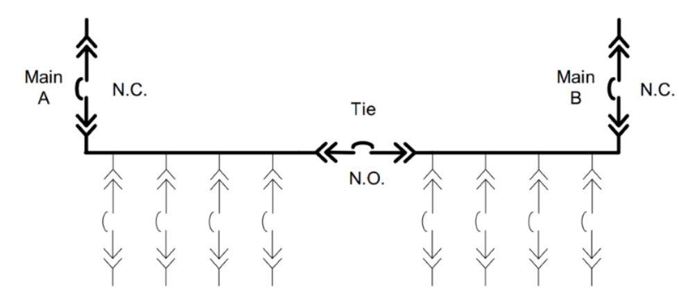
Figure 1 — Typical Main-Tie-Main Redundant source electrical system. Power Factor Correction
on these systemsrequires two capacitor banks, one for each bus.
Typical Control Methods
Power capacitor banks and harmonic filter banks on redundant source electrical systems typically employ either master-slave controls or use main-tie current transformers (CTs) to achieve automatic control in normal plant operation with tie open, and in abnormal condition, with one main open and the tie closed.

Master-Slave Control
In this type of control, each power capacitor bank acts as a “master” when the tie breaker is open, each controlling the power factor of their connected bus based on voltage and current signals from their main circuit breaker (referred to as “master-master” control mode) CT’s and Potential Transformers (PT’s). When the tie breaker is closed (with one main circuit breaker open), the capacitor bank with the closed main breaker becomes the “master” while the other capacitor bank becomes the “slave” (referred to as “master-slave” control mode). The “master” bank controls the opening and closing of both capacitor banks. This system has several draw backs, and NEPSI does not recommend it. Drawbacks include:
- The PLC program is complicated
- Open and close signals must be wired between the master and the slave capacitor banks control panels
- When closing or opening the tie breaker, the system must be switched from “master-master” control mode, to “master-slave” control mode. The transition between modes is complicated by required discharge times.
- Changing between “master-master” and “masterslave” control modes can be made automatic, but requires additional sensing of “a” and “b” contacts from the main and tie circuit breakers. Many customers treat this as a manual operation and use a “master/slave” control switch on the control panel to put the bank into “master” or “slave” control mode.

Main and Tie Current Transformers
In this type of control, current transformers located on both the tie and main circuit breakers are wired to provide the necessary current signals to control both banks for all main and tie breaker configurations. No special control operations are required when changing from open-tie to close-tie operation. Figure 2 shows a 4 CT arrangement, while figure 3 shows a 3 CT arrangement.
NEPSI recommends using tie CT’s for control (instead of “master-slave” arrangement) for the following reasons:
- Each power capacitor banks controls the load power factor on its own bus. No matter the position of the tie or main circuit breakers.
- No communication between power capacitor banks is required.
- No action needs to be taken when the tie and main breaker status is changed. The controls transitions automatically.
- The capacitor banks and controls for both banks are identical.
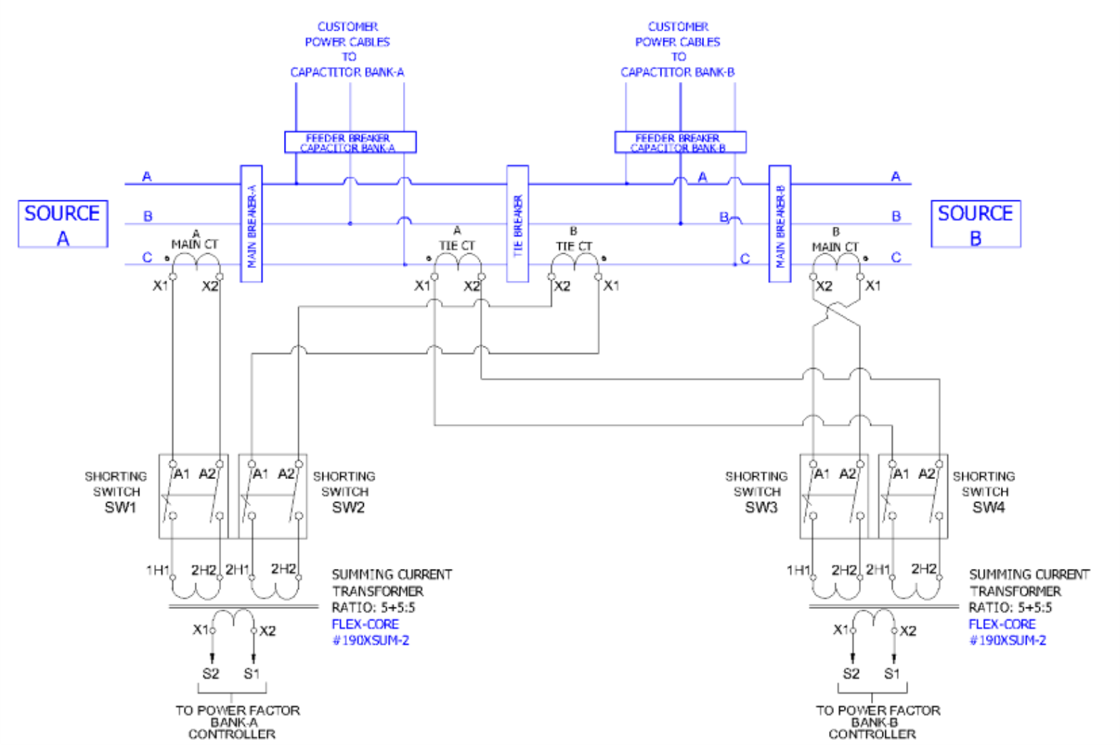
Figure 2 — Four CT arrangement. Separate Tie CT's are used by the
power factor/var controller on bus A and bus B.

Figure 3 — Three CT arrangement. The Tie CT is shared by the
power factor/var controller on bus A and bus B. This arrangement requires
secondary CT wires between the two capacitor banks.
Implementation Guidelines
The following guidelines must be followed with implementation of the tie CT control scheme:
- CT’s must be of equal rating.
- CT’s must all be on the same phase.
- It is important to not pick a current transformer ratio that is to high (i.e. do not pick the switchgear rating of 2000 amps if the expected load is only 500 amps). Two 2000/5 CT’s summed through a summing CT will result in a ratio of 4000/5 to the power factor controller. This can amount to a low current signal to the PF controller.
- Summing CT’s and shorting switches should be mounted in the capacitor bank control panel.
- Polarity must be correct for all CT’s.

Follow us on social media for up-to-date news, videos, and other information: