
The Most Trusted Name in Power Factor Correction and Harmonic Filtering
MEDIUM VOLTAGE - MOTOR SURGE PROTECTION (MSP)
NEPSI's MSP (Motor Surge Protector) is designed to protect medium voltage motors from voltage surges due to lightning and switching events.
The MSP accomplishes this task better than any other product in the market by decreasing the slope and crest of impending voltage surges to safe levels.
Application of the MSP is guaranteed to reduce the likelihood of motor failures, resulting in less down-time and higher productivity.
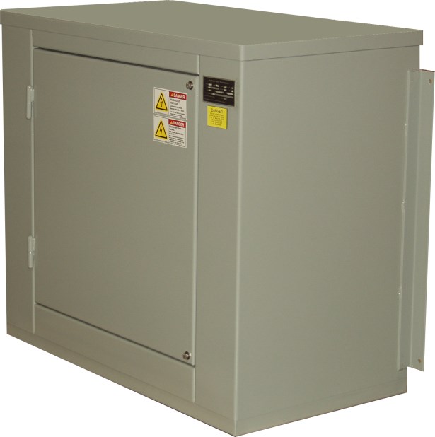
Figure 1 - NEPSI's Medium Voltage Motor Surge Protection equipment protects motor insulation from power system transients.
- Reduced medium voltage motor failures from voltage surges due to lightning, faults, and switching events
- Units can be custom designed for direct mounting to generators, motor, and compressor housing
- Units can be supplied with over-current and differential protection current transformers
- Reduced downtime and material waste from motor failure
- Simple to install and requires no maintenance
- MSP's are custom designed for many OEM’s utilizing medium voltage motors and generators.

Figure 2 - Principle operation of the MSP is to decrease the crest voltage and rate of rise of the impending surges. High rates of rise damage end turns
while high crest voltages damage winding to core insulation. Both of
these types of damaging surges are mitigated with NEPSI's MSP.
Due to the wavelength and travel time of lightning and switching transients, the MSP is most effective when placed as close as practical to the motor termminals with the ground leads being as short as possible. This will limit the surge voltage seen by the motor to the discharge voltage of the arrester.
For best protection, one MSP should be placed at each medium voltage motor or generator.
Where there are many small motors or explosion proof motors in hazardous locations, a single MSP at the motor control center is recommended.
The proper choice of MSP is based on the system and/or motor voltage and the system grounding. The order guide below can be used to determine the correct MSP for your application.
Enclosure
11 Gauge Galvanneal Steel all welded construction. Base of unit consists of C2 steel channel for floor mounting and skidding into place. Wall mounting flanges are available for placement on suitable walls. Meets NEMA requirements for 1, 3R, 12 as standard (4X available as an option). A swing-out door with stainless steel hinges is provided for maintenance and termination.
Surge Capacitor
The MSP is equipped with hermetically sealed low-loss, low-inductance surge capacitors. Their capacitance rating is based upon the MSP voltage rating as shown in Table 1 below. The surge capacitor is equipped with discharge resistors that reduce the residual voltage on the capacitor to 50 volts in 5 minutes.
Wall Mounting Flanges
Allows the MSP to be mounted on a suitable wall.
Surge / Lightning Arresters
The MSP is equipped with heavy duty distribution class, silicone rubber housed MOV lightning arresters (station class are available as an option) incorporating the latest in metal oxide varistor (MOV) design techniques. The high track resistant, non-fragmenting silicone rubber housed arrester provides increased safety for personnel and equipment. The lightning arresters complies with the latest revision of ANSI/IEEE C62.11 "IEEE Standard for Metal Oxide Surge Arresters for AC Power Circuits.
Terminals
The MSP is provided with a Copper NEMA 2-hole pad for interconnection with customer wiring.
Operating Temperature
-40°F ( -40°C) to +115°F (+46°C)
Warranty
1 year replacement on parts per NEPSI standard warranty.
Fuses
Increases system and equipment reliability by re-moving a failed MSP. Blown fuse detection is provide through a set of dry contacts to alert plan personnel of a blown fuse.
Differential Current Transformers
This option is shown in Figure 3, below. The differential CT’s are placed inside the MSP and afford the highest level of protection for the motor or generator.
Pecker-Head / Motor Terminal Mounting
The MSP can be custom designed for direct mounting to a motor or generator to act as a terminal box. The equipment can be equipped with a neutral grounding resistor, differential CTs, and ground CTs to provide all fault sensing.
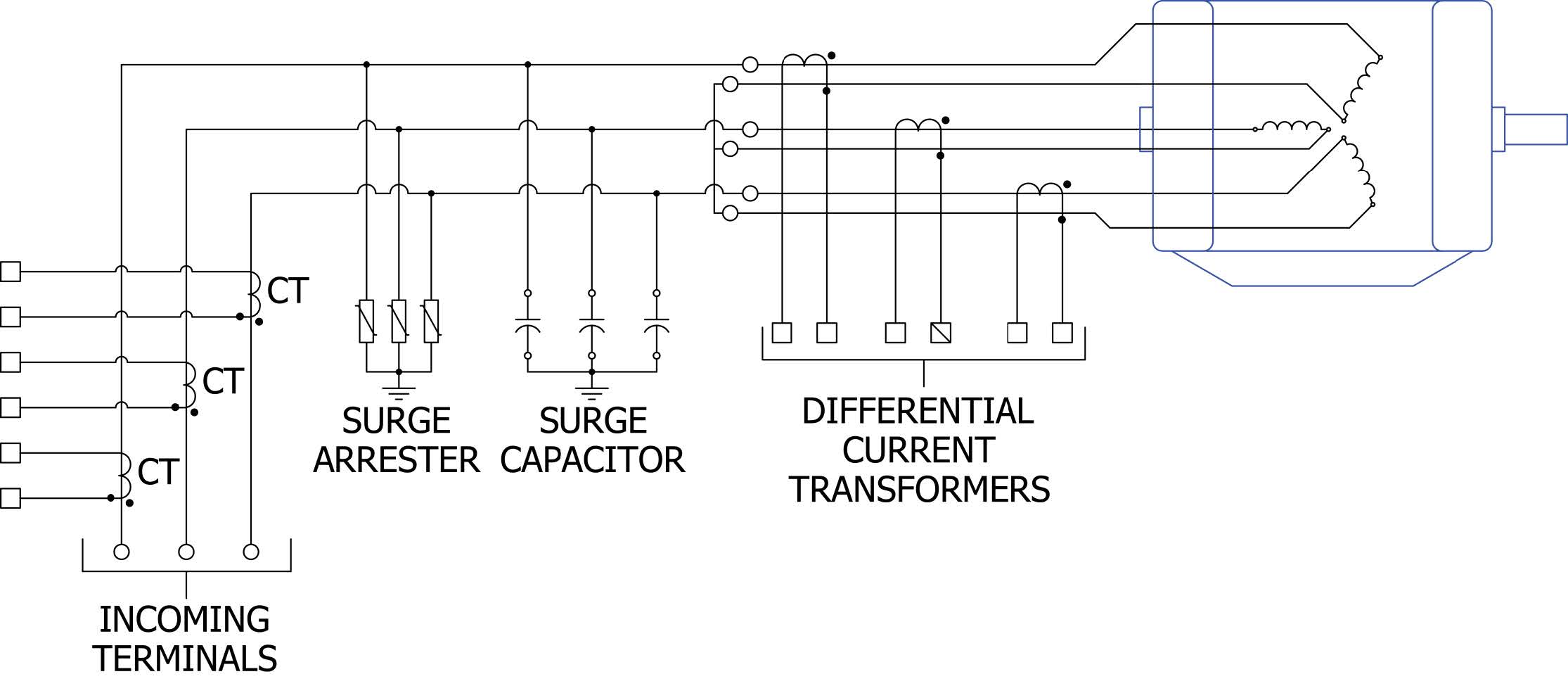
Figure 3 - Three-line diagram of MSP equipped with differential current transformers and
phase overcurrent transformers for connection to motor protection relays.
The MSP can be ordered by choosing the part number from the table below based on the system voltage and type of grounding. Options are ordered by adding part number suffixes.
| Table 1 Catalog Numbers for Motor Surge Protectors | ||||
| System Voltage | Recommended Part Number | |||
| Nominal | Maximum | Four-Wire Wye Multi-Grounded Neutral | Three-Wire Wye Solidly-Grounded Neutral | Delta, Resistive Grounded and Ungrounded Wye |
| 2.4 | 2.54 | - | - | MSP3A0240 |
| 4.16/2.4 | 4.4Y/2.54 | MSP3A0416 | MSP6A0416 | MSP6A0416 |
| 4.16 | 4.4 | - | - | MSP6A0416 |
| 4.8 | 5.08 | - | - | MSP6A0416 |
| 6.9 | 7.26 | - | - | MSP9A0690 |
| 8.32Y/4.8 | 8.8Y/5.08 | MSP6A1380 | MSP6A1380 | - |
| 12.0Y/6.93 | 12.7Y/7.33 | MSP9A1380 | MSP12A1380 | - |
| 12.47Y/7.2 | 13.2Y/7.62 | MSP9A1380 | MSP15A1380 | - |
| 13.2Y/7.62 | 13.97Y/8.07 | MSP10A1380 | MSP15A1380 | - |
| 13.8Y/7.97 | 14.52Y/8.38 | MSP10A1380 | MSP15A1380 | - |
| 13.8 | 14.52 | - | - | MSP15A1380 |
| 20.78Y/12.0 | 22Y/12.7 | MSP15A2400 | MSP21A2400 | - |
| 22.86Y/13.2 | 24.2Y/13.87 | MSP18A2400 | MSP24A2400 | - |
| 23 | 24.34 | - | - | MSP24A2400 |
| 24.94Y/14.4 | 26.4Y/15.24 | MSP18A2400 | MSP27A2400 | - |
For the addition of optional accessories, append the corresponding suffixes from the table below.
| Table 2 Part Number Suffixes | |
| Station class Lightning Arresters | S |
| Current Limiting Fuses | CLF |
| Over-Current CTs | OVCT |
| Pecker-Head/Motor-Generator Terminal Box Mounting | PHM |
| Neutral Grounding Resistor | GR |
| Differential Current Transformers | DCT#### * |
| * For differential current transformer option, specify the desired primary current rating of the CT where #### appears. | |
| Table 3 MSP Dimensions, Weights, and Electrical Values | ||||||
| Part Number | Height (Inches) | Width (Inches) | Depth (Inches) | Capacitance Rating of Surge Capacitor (Micro-Farads) | Surge Arrester Duty Rating (kV) | Weight (Pounds) |
| MSP3A0240 | 39.0 | 43.0 | 24.0 | 0.5 | 3.0 | 310 |
| MSP3A0416 | 39.0 | 43.0 | 24.0 | 0.5 | 3.0 | 310 |
| MSP6A0416 | 39.0 | 43.0 | 24.0 | 0.5 | 6.0 | 310 |
| MSP9A0690 | 43.0 | 43.0 | 24.0 | 0.5 | 9.0 | 420 |
| MSP6A1380 | 47.0 | 43.0 | 24.0 | 0.25 | 6.0 | 420 |
| MSP9A1380 | 47.0 | 43.0 | 24.0 | 0.25 | 9.0 | 420 |
| MSP10A1380 | 47.0 | 47.0 | 24.0 | 0.25 | 10.0 | 420 |
| MSP12A1380 | 47.0 | 47.0 | 24.0 | 0.25 | 12.0 | 420 |
| MSP15A1380 | 47.0 | 47.0 | 24.0 | 0.125 | 15.0 | 420 |
| MSP15A2400 | 47.0 | 47.0 | 24.0 | 0.125 | 15.0 | 470 |
| MSP21A2400 | 51.0 | 51.0 | 28.0 | 0.125 | 21.0 | 470 |
| MSP24A2400 | 51.0 | 51.0 | 28.0 | 0.125 | 24.0 | 470 |
| MSP27A2400 | 51.0 | 51.0 | 28.0 | 0.125 | 27.0 | 470 |
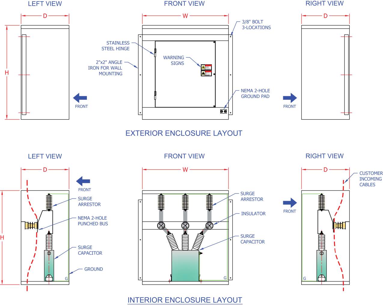
Figure 4 - Approximate layout for basic MSP. Layout and dimensions may change without notice.
Confirm layout and dimensions at order placement.
GUIDE FORM SPECIFICATIONS |
|||
| Guide Form Specification for Motor Surge Protection |  |

Follow us on social media for up-to-date news, videos, and other information: