
The Most Trusted Name in Power Factor Correction and Harmonic Filtering
METAL-ENCLOSED HARMONIC FILTER BANKS...
Share this product page:
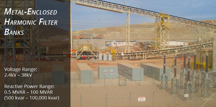
NEPSI's Medium Voltage Metal-enclosed Harmonic Filter Banks are custom designed for application on industrial, commercial, and utility power systems that require medium voltage power factor correction, var and voltage support, and mitigation from harmonic resonance or harmonic distortion. The harmonic filter banks are configurable as fixed or automatic controlled with 1 or more stages at voltages from 2.4kV through 38kV (60kV BIL through 200kV BIL).
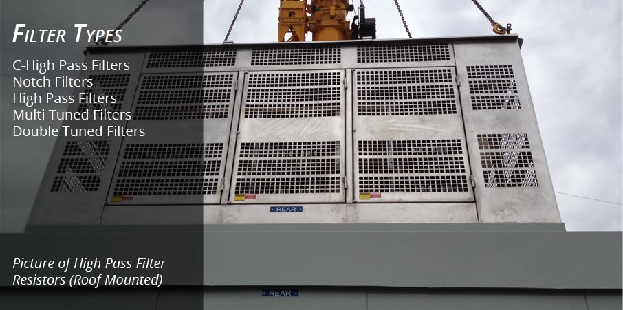
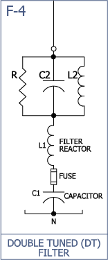
Available filter types include C-High-Pass (damped filters), High-Pass, Notch (Band-Pass), double-tuned, and multi-tuned filters. NEPSI's filters find wide application in many different industries including wind, mining, paper, chemical, and petroleum.
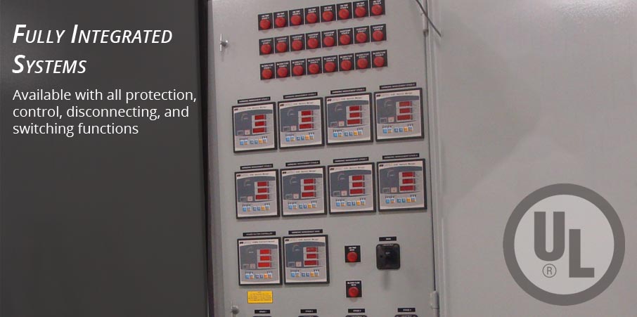
The filter banks are designed and customized by NEPSI to meet site and system requirements and can be configured to include some or all protection, control, switching, disconnecting and grounding functions.
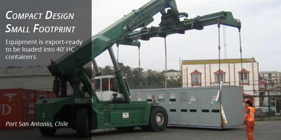
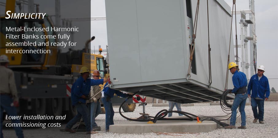
Harmonic filter banks are designed for placement in outdoor or indoor substations and come fully assembled, tested, and ready for interconnection.
...FOR POWER FACTOR CORRECTION AND HARMONIC MITIGATION
Medium Voltage Metal-enclosed Harmonic Filter Banks offer many features and benefits over traditional open air (stack-rack) filter banks. When all costs are considered, including engineering, integration, site preparation, installation, maintenance, and liability, the Metal-Enclosed Filter Bank Design is the favorable choice.
The following table summarizes the many features and benefits of applying metal-enclosed filter banks to your system.
BENEFITS |
FEATURES |
Economic |
Fully assembled and ready for interconnection - Fast, easy installation Fully tested and calibrated - reduced startup and commissioning cost Small footprint - Less site preparation cost and associated risk Less engineering cost - with NEPSI's experience comes engineering efficiency |
All-Inclusive Design |
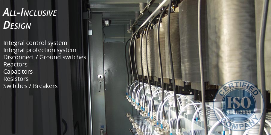
Integral disconnect, ground switch, and/or circuit breakers Single-phase and 3-phase iron-core reactors (inductors) High-pass stainless steel grid resistors for high-pass and C-high-pass filters Capacitor switches for stage or filter branch switching Integral control and protection system with manual and automatic controls Individually fused capacitors rated for harmonic filter duty Internal PTs and CTs for control, metering, and protection Surge protection |
Performance |
Reduces harmonic voltage and current distortion (higher power quality for your facility) Prevent or dampen unwanted harmonic resonances Reduces kVA billing and power factor penalties Improves voltage profile Var support for IPP interconnect requirements Release system capacity (Increases power flow capability) |
Reliability |
Key components are protected from wildlfie and atmospheric contaminants More likely to be maintained as equipment is at ground level Designed and built by an ISO 9001:2015 certified company with a proven track record of quality and performance |
Simplicity |
Easy to purchase - Single vendor for the entire project Fully integrated design - Leave the design, assembly, setting, calibrating, testing, and commissioning to NEPSI |
Durability |
Resists effects of corrosion, dust, solar radiation, snow, and rain Marine based paint system over galvanneal steel All stainless steel hardware Seismic, wind, and snow load rated |
Safety |
Enclosure protects against inadvertent contact Key interlock system for safety and proper sequence of operation |
Flexibility |
Equipment that matches your needs - Configured to your site's electrical and physical requirements Designed to meet your performance goals |
NEPSI's harmonic filter banks are rated and configured to meet customer requirements for voltage, basic insulation level (BIL), available short circuit current, reactive power rating, and frequency. Internal components such as disconnect and grounding switches, circuit breakers, capacitors, capacitor switches, and capacitor fuses are chosen based on their ratings, costs, availability, and NEPSI's experience with the supplier's quality, service, and reliability.
RATING |
RANGE OF AVAILABLE RATINGS |
|---|---|
| Bank Configuration: | Fixed, Switched, Single Step, Multiple Step |
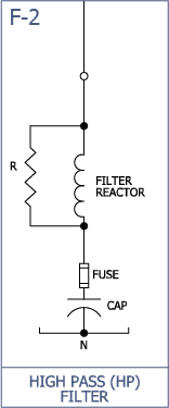
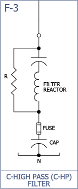
| Filter Types: | Notch (Band-Pass), High-Pass, C-High-Pass, Double-Tuned, Multi-Tuned |
| Operating Voltage (line-to-line): | 2.4kV – 38kV |
| Operating Frequency: | 50 Hertz | 60 Hertz |
| Reactive power output: | 0.5MVAR – 100 MVAR (500kvar – 100,000 kvar) |
| Tune frequency (Hz) | 85 Hz 2100 Hz (500kvar – 100,000 kvar) |
| High-Pass (damping) resistor rating: | 1 ohm to 1000 ohms 10kW/Phase - 200kW/Phase |
| Short circuit (asymmetrical momentary): |
16kA - 61kA |
| Impulse withstand voltage (Basic Insulation Level): |
60kV – 200 KV |
| Short-time withstand voltage (1 minute 50/60 Hertz): |
19kV – 100kV |
| Control voltages: | AC Volts: 110, 115,120, 220, 50/60hz DC Volts: 24, 48, 110, 125, 220 |
| Operating temperature range: | -50°C to +55°C -58°F to 131°F |
| Maximum altitude without de-rating: | 1,000 Meters 3,300 Feet |
| Enclosure: | (NEMA): 1, 3R, 4X, 12 (IEC): IP10, IP14, IP56, IP52 Arc Flash Mitigation: Passive & Active Hazardous Locations: NEC Class 1 & 2, Div. II |
| Seismic: | As specified - Zone 4 |
| Capacitor fusing: | Internally fused | Externally fused |
NEPSI's metal-enclosed harmonic filter banks are custom designed and configured to meet a wide variety of requirements, including filter type, tuning point, switching, disconnecting, grounding,protection, and control. The more typical types and configuration options are provided below. Feel free to contact NEPSI for types and configurations not shown.
The physical arrangement of the filter bank and component layout are customized to meet site constraints and requirements.
Click each of the headings below to learn more about our filter bank configurations.
 INCOMING COMPARTMENT CONFIGURATION OPTIONS
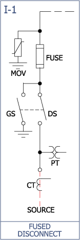
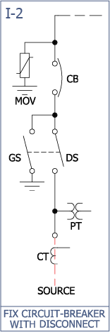
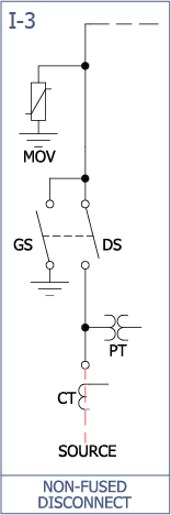
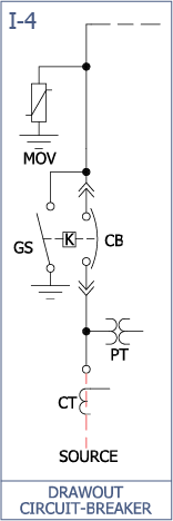
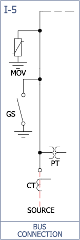
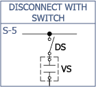
The incoming compartment, where power is connected to the harmonic filter bank, is normally configured based on the availability of existing breakers, disconnect switches, and the rating of the filter bank. Typical configurations options are provided below.
ACCESSORIES FOR INCOMING COMPARTMENT
The following items are available for placement in the incoming compartment.


 CAPACITOR / IRON-CORE REACTOR COMPARTMENT CONFIGURATION OPTIONS
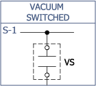
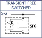
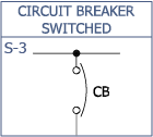
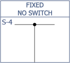
The capacitor compartment may consists of one filter bank or multiple capacitor stages. A filter bank or stage normally consists of the capacitors, capacitor fuses, and where applicable, a switching device and inrush reactors. Typical bank or stage configuration options are provided below. The filter bank/stage compartment is compartmentalized and isolated from the incoming compartment to allow for maintenance and repair.

 FILTER BANK / STAGE CONNECTION
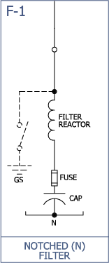
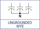
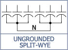
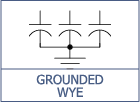
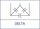
The harmonic filter bank can be connected in a number of different ways depending upon bank rating and protection requirements. Typically, filter banks are provided with an ungrounded wye or ungrounded split-wye connection, but a grounded wye and Delta connection are also available.
Component selection is based on specified control and protection requirements, harmonic filter bank configuration, short circuit requirements, voltage, BIL, reactive power rating, frequency, costs, and NEPSI's experience with component quality and reliability. The following list provides key components and features commonly supplied by NEPSI.
Click each of the headings below to learn more about our commonly used components
INCOMING COMPARTMENT
Air Disconnect Switch
Externally operated chain-drive operated 3-pole air-disconnect switch to provide a "visible-break" and electrical isolation of the harmonic filter bank during maintenance and repair.
Ground Switch
Externally operated chain-drive or direct-drive operated 3-pole ground switch to ground the load-side terminals of the incoming air-disconnect switch, breaker, and/or capacitors for safety during maintenance. The ground switch is key interlocked with the upstream disconnecting device to prevent closing of the ground switch onto a live bus.
Main Incoming Fuses
Main incoming current limiting fuses (with local and remote blown fuse indication) for short circuit protection of the harmonic filter bank.
Main Incoming Breaker
Main incoming drawout or fixed-mounted circuit breaker for protection, isolation, and switching of the harmonic filter bank.
Lightning Arresters
Lightning arresters are provided as standard to protect the harmonic filter bank and incoming cables from lightning and switching transients.
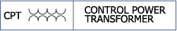
Control Power Transformer(s) (CPT)
Control power transformers to supply control power and voltage sensing to the filter bank's, metering, protection, and control system.
Current Transformers (CT)
Current tranformers to supply a current signal for the filter bank's metering, protection, and control system.
Bus Duct Entry
Bus duct entry to allow for direct bus connection to switchgear.
Dead-Front Entry
Dead-front design entry that allows for 200 amp and 600 amp separable elbow connectors.
Roof Bushing Entry
Roof bushing entry to allow for direct connection to overhead bus within substations.
CAPACITOR / IRON CORE REACTOR COMPARTMENT
Capacitors
Low loss, double bushing capacitors that meet or exceed IEC 871, IEEE 18 and CSA standards. Capacitors are typically connected ungrounded-wye or ungrounded split-wye. Internal discharge resistors reduce the residual voltage to less than 50 volts within 5 minutes of de-energization. The dielectric fluid is environmentally friendly, biodegradable, non PCB, with low toxicity. Internally fused capacitors are available upon request.
Capacitor Fusing
Capacitors are individually fused with current limiting fuses. These fuses reduce the possibility of case rupter on capacitor failure and allow the harmonic filter bank to continue to operate when a capacitor fails. The fuses are equipped with blown fuse indicators and can also be equipped with direct fuse operation sensors for blown fuse detection.
Capacitor Switches
Single stage and multi-stage harmonic filter banks are equipped with vacuum contactors (for voltages less than 6.6kV), capacitor switches, or circuit breakers (fixed or drawout) for capacitor switching.
Iron Core Filter Reactors
Iron-core filter reactors provide the necessary inductance (inductive reactance) to tune the capacitor bank to the desired frequency. In addition to tuning, the reactors significantly reduce the frequency and magnitude of inrush currents from back-to-back capacitor bank switching.
High Pass Filter Resistors
Stainless steel Grid Reistors are provided for C-High Pass, High-Pass, and Double-Tuned Harmonic Filters. Resistors are of a stainless steel stamped grid design that offer compact high wattage capability, low temperature coefficient, and corrosion resistance.
Current Transformers
Multi-stage or multi-tuned harmonic filter banks can be equipped with current transformers to provide a current signal for metering and protection. Current transformers can be provide to monitor both iron-core reactor current as well as high-pass resistor current.
Air Disconnect Switch
Externally operated, key interlocked, 3-pole air-disconnect switch(s) that isolates a single stage of a multi-stage filter bank, allowing for partial bank operation during maintenance.
Ground Switch
Externally operated, key interlocked, 3-pole ground switch(s) that grounds the capacitor terminals to ensure all trapped charge has been removed from the capacitors.
CONTROL AND PROTECTION COMPARTMENT
Automatic Filter Bank Controllers
Automatic harmonic filter Banks are equipped with various types of controllers to automatically turn harmonic filter banks (stages) on and off based on var flow, power factor, harmonic distortion, watt flow, voltage level, current-flow, time-of-day, or day-of-week. Controllers are integrated with the protection system and other components to form a fully integrated system.
Protection
Harmonic filter Banks can be equipped with various protection relays, meters, and sensors to protect the filter bank as well as the system from over-voltage, out-of-balance operation from capacitor failure, internal faults and over-temperature due to fan failure. Protection devices are integrated with the control system and other components to form a fully integrated system.
Arc Flash Mitigation
See NEPSI’s technical note on arc flash mitigation in metal-enclosed capacitor banks and harmonic filter banks. This technical note provides over 30 mitigation strategies available from NEPSI to minimize the level of exposure to arc flash events as well as ways to reduce the probability that an arc flash event will occur in the first place.
 MISCELLANEOUS
Enclosure
Free standing, compartmentalized, all welded, 11 gauge galvanneal steel construction with 3 point pad-lockable latching handles and stainless steel hinges. The enclosure is painted with Engineered Siloxane, a Marine paint with rated salt spray of 5500 hours. NEMA 3R (IP64) construction is standard, NEMA 12 (IP65) and 4X (IP66) are available as an option. Base of enclosure as well as capacitor supports are formed from C4 structural steel. Door stays and windows are standard.
Key Interlock System
Key interlock system are available that dictate sequence of operation and safe entry into the enclosure. Upstream devices may be included in the interlock sequence.
Ground and Phase Bus
A 1/4" X 2" Tin plated ground bus is provided through the width of the enclosure to assist in grounding during maintenance. All phase bus is Tin plated square edged and rated at a minimum of 135% of the bank nominal current rating.
NEPSI's Metal-enclosed Harmonic Filter Banks can be furnished with an integrated protection system that is located in an isolated compartment that is integral with the harmonic filter bank enclosure, or located remotely in an E-house or control room. Whether integrally mounted, or remotely located, NEPSI's protection systems are completely tested, set, and calibrated at the factory before shipment.
All Harmonic Filter Banks need to be protected from abnormal conditions that are both external and internal to the filter bank. External conditions that may be destructive to the harmonic filter bank can arise from over/under voltages, faults, and harmonic distortion. Internal conditions can be from internal faults, failed capacitors, harmonic resonance, and over temperature. The need to protect for these conditions must be considered when purchasing a harmonic filter bank.
The Table below summarizes the protections that are available from NEPSI. Depending on configuration of the incoming compartment, (see the configure tab) some of these protections may not be applicable and would need to be provided by the upstream switchgear.
The recommended protections are as follows:
PROTECTION TYPE |
DESIGNATION |
PROTECTION DESCRIPTION |
|---|---|---|
| Short Circuit and Overcurrent Protection |
50/51 50/51G |
Short Circuit and Overcurrent protection needs to be provided either as part of the harmonic filter bank or upstream by the customer. This protection is provided by current limiting fuses or by a circuit breaker with associated relaying. |
| Over-Voltage | 59 | To detect an overvoltage condition that could result in capacitor failures and to reduce supply voltage by turning the bank off. Typically an over voltage relay with multiple set points is provided to first alarm and take corrective action, and if necessary then trip if an overvoltage persist. |
| Under-Voltage | 27 | To detect an under voltage condition to disconnect the filter bank if required due to trap charge on re-energization or to protect the upstream device that will be restoring power. |
| Neutral Unbalance (Blown Fuse Detection) |
59N or 51N or 51G or Direct |
To detect a capacitor fuse operation. This protection is critical as a blown fuse condition will result in some de-tuning of the harmonic filter bank and may result in resonance that could fail the harmonic filter bank or damage other equipment on the customer supply. |
| Harmonic Voltage & Current Distortion |
Ithd, Vthd | Protection against harmonic resonance that can result in high currents or voltages. This protection also serves as backup for blown fuse detection listed above. |
| Over-Temperature | 26 | Over-temperature detection to protect capacitor cells in the event of an over temperature condition due to a fan failure or improper air flow. |
| Over-Load | 49 | Over-load protection of the harmonic filter is critical for the protection of the iron-core reactors. The overload relay should be sensitive to RMS current associated with the filter's fundamental current and harmonic current. Overloads may occur due to harmonic resonance, misaplication, detuning, or an increase in nearby non-linear load(s). |
| Arc Flash Protection | -- | ABB UFES System; arc flash protection relay and ultra fast earthing switch to eliminate arcing faults in less than 4 mS. See NEPSI’s arc flash mitigation document for further details on arc flash mitigation. |
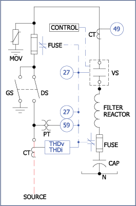
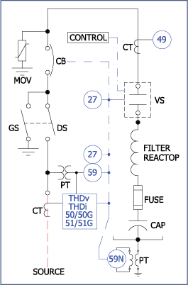
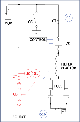
PROTECTION EXAMPLES
NEPSI's Metal-enclosed Harmonic Filter Banks can be furnished with an integrated control system that is located in an isolated compartment that is integral with the harmonic filter bank enclosure, or be located remotely in an E-house or control room. Whether integrally mounted, or remotely located, NEPSI's control systems are completely tested, and set at the factory to ensure easy, and problem free installation and commissioning.
The control system normally consists of a program logic controller (PLC) and other metering, control, comunication, and indicaton devices that are necessary for the safe and proper operation and monitoring of the filter bank. The table below provides the more common control features and options provided by NEPSI.
FILTER BANK CONTROL OPTIONS |
|---|
| Power Factor Control |
| Var Control |
| Voltage Control |
| Harmonic Voltage / Current Distortion Control |
| Remote / SCADA Control |
| Manual Control |
| Time-of-Day |
| Day-of-Week |
TYPICAL CONTROL FEATURES |
|---|
| On/off indicators for all switching devices |
| On/Off/Auto Control Switches for each capacitor stage |
| Local/Remote Switches |
| Circuit Breaker Control Switches |
| 5-minute discharge timers |
| Power quality meters |
| Control inputs for prohibiting improper bank operation |
| Control Power Circuit Breaker |
| Key and electrical interlocks |
| Lights |
| Strip Heaters |
| Thermostatically controlled exhaust fans |
| Shorting Switches/blocks for all current transformers |
PRODUCT LITERATURE |
|||
| Metal-Enclosed Harmonic Filter Banks |  |
||
| Iron Core Filter Reactors | |
||
| High Pass Filter Resistors | |
GUIDE FORM SPECIFICATIONS |
|||
| Harmonic Filter and Capacitor Bank Application Studies Spec. | |
||
| Metal-Enclosed Harmonic Filter Banks - Wind Farm Applications | |
||
| Metal-Enclosed Harmonic Filter Banks - Chemical / Large Rectifier Applications | |
||
| Metal-Enclosed Harmonic Filter Banks - General / Industrial Applications | |
||
| Metal-Enclosed Harmonic Filter Banks - Chip Fabrication Applications | |
||
| Metal-Enclosed Harmonic Filter Banks - Mining Applications (with feeder bus) | |
||
| Metal-Enclosed Harmonic Filter Banks - Mining Applications (without feeder bus) | |
||
| Metal-Enclosed Harmonic Filter Banks - Solar Applications | |
RELATED PRODUCTS AND SERVICES |
|||
| Power System Studies | |
||
| Metal-Enclosed Capacitor Banks | |
||
| Hybrid Shunt Reactor and Shunt Power Capacitor Banks | |
||
| Data Request for Harmonic Filter and Power Capacitor Design Studies | |
HELPFUL INFORMATION AND TOOLS |
|||
| Technical Notes | |||
| Calculators | |||
| Metal-Enclosed vs. Open Rack Configuration | |
||
| Filter Design Calculation | |||
| Arc Flash Hazard Mitigation in Metal-Enclosed Power Capacitor Banks and Harmonic Filter Banks | |

Follow us on social media for up-to-date news, videos, and other information: