
The Most Trusted Name in Power Factor Correction and Harmonic Filtering
PRODUCTS
NEPSI manufactures various medium voltage metal-enclosed products to mitigate common power quality concerns. Review NEPSI's product offering below to determine what product(s) you need. Feel free to contact NEPSI for technical assistance.
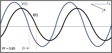
Capacitor Banks
Metal-enclosed power capacitor banks and harmonic filter banks correct for poor power factor. Consider shunt power capacitor banks if your system does not have a resonance concern and significant harmonic producing loads. If harmonic resonance is a concern, or if you require harmonic attenuation, you should consider harmonic filters.
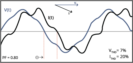
Harmonic Filter Banks
Metal-enclosed harmonic filter banks reduce harmonic voltage distortion, harmonic current distortion, and improve power factor. Consider this product if you have resonance concerns or significant harmonic producing devices on your system and you need power factor correction.
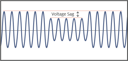
actiVAR
Consider a actiVAR when instantaneous var support is need to mitigate voltage sags, voltage flicker, and high inrush currents associated with starting and impact loading of large motors and dynamic loads. This equipment stabilizes your system voltage, helps your equipment run more smoothly, and increases your systems efficiency and throughput.
Hybid designs that include conventionally switched harmonic filters for power factor correction and harmonic attenuation are also available.
MV-TVSS
NEPSI's offers various surge protection products. Consider the MV-TVSS (medium-voltage transient voltage surge suppressor) product offering if you are looking to protect your service entrance from system transients. The MSP (Motor Surge Protector) is designed for placement near motors to protect motor windings from system surges. RC Snubbers are designed to protect potential transformers and power transformers from ferroresonance produced by switching transients associated with opening and closing of nearby vacuum circuit breakers.
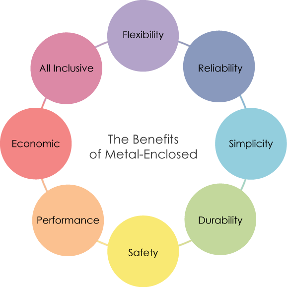
Medium Voltage Metal-Enclosed Banks offer many features and benefits over traditional open air (stack-rack) banks. When all costs are considered, including engineering, integration, site preparation, installation, maintenance, and liability, the Metal-Enclosed Bank design is the favorable choice.
 Metal-Enclosed banks come fully assembled, tested, calibrated, and ready for interconnection - leading you to reduced installation and engineering costs at startup. Compared to the open-air rack alternative, this specific equipment leaves a 20% less footprint and potentially saves up to 85% in terms of required space.
 By utlizing NEPSI capacitor banks, you can expect to improve your voltage profile and power flow capacity. In turn, this will reduce kVA billing and power factor penalties.
 Compared to open-air racks, metal-enclosed banks pose significantly less risk associated with the maintenance of your equipment - no cranes, ladders, or lifts necessary. The key interlock system assures proper sequence of operation while the enclosure constantly protects against inadvetent conact.
 All stainless steel hardware creates resistance from the negative effects of corrosion, dust,
radiation, snow, rain, etc. Compact design and structural stability offer better seismic performance. NEPSI's equipment can also be certified and rated for specific seismic, wind, and snow load conditions.
All stainless steel hardware creates resistance from the negative effects of corrosion, dust,
radiation, snow, rain, etc. Compact design and structural stability offer better seismic performance. NEPSI's equipment can also be certified and rated for specific seismic, wind, and snow load conditions.
 NEPSI's top level personnel have over 25 years of experience in the design, development, and analysis of industrial, utility, and commercial power systems and power factor correction equipment. Allow us to handle the design, development, assembly, testing, and commissioning.
 NEPSI is an ISO 9001:2015 certified company. Our third-party approved quality management system assures that your equipment is carefully constructed, properly tested, and long-lasting. Customers have rewarded NEPSI a 4.3 / 5.0 star rating - proving our commitment to quality and performance. The key components inside of your enclosure are protected from both wildlife and atmospheric contaminants.
 This equipment is custom built - for you - from the very beginning. Starting at the design stage, NEPSI is able to create custom equipment configured to your site's electrical and phyical requirements. Years of shipping experience allow us to load into ocean containers, flat beds, open-racks, or whatever other means of transportation it takes to get to your site.
 NEPSI capacitor banks provide a single, fully integrated solution for your power factor correction needs. This includes: integral disconnect & grounding switches, circuit breakers, capacitor switches for multi-stage banks, automatic / manual controls, protection systems, and internal
PTs / CTs, among numerous other options.
NEPSI capacitor banks provide a single, fully integrated solution for your power factor correction needs. This includes: integral disconnect & grounding switches, circuit breakers, capacitor switches for multi-stage banks, automatic / manual controls, protection systems, and internal
PTs / CTs, among numerous other options.

Follow us on social media for up-to-date news, videos, and other information: